Monday, March 10, 2008

Project: Connector Assembly Structure (A#1)

Project: Connector Assembly Structure (A#1)

clip_image037

Completion Time: 10 Minutes

Prerequisites

  • Knowledge of Assembly structures

Objective: An introduction to Assembly Design. Emphasizing assembly terminology by creating new assembly documents and manipulating component properties.

Process: The objective of this exercise is to bring in existing components into the assembly structure and adjust the assembly structure in the specification tree through the properties page.

Instructions

1: First let's set the units to inches.

Step 1 - Details

In the Tools pull-down menu, select Options + Parameters and Measure. Select the Units tab and set Length to Inch (in). Select OK to exit.

2: Next Open up a new Product

clip_image039

Step 2 - Details

Select File + New. Select Product in the New dialog window. Select OK.
Note – If the Assembly Design workbench is already active, initiating the Assembly Design workbench will create an additional Assembly Design document window. The number that occurs right after the word Product in the specification tree indicates how many similar documents have been opened or initiated in the current session.

3: Change the Product name by doing clicking the Right Mouse Button (RBM) on the "Product1" component in the specification tree and pull up the properties dialogue box and change the Product Name to Connector Assembly Structure.

clip_image040

4: Now add parts and sub-assemblies to the empty assembly using the "Existing Component" operator in the Product Structure ToolBar clip_image041  . Select Exiting Component. Then select the product "Connector Assembly Structure" to access the file query dialogue box

clip_image043

Insert the "ConnectorShell.CATPart" and the "ConnectorCardAssembly.CATProduct"

clip_image044

Step 4 - Details

Hold the Ctrl key down to multi-select the two components

5: RMB on the ConnectorShell.CATPart. Copy and Paste it onto the Connector Assembly Structure branch.

clip_image045

The result will be another instance of the Connector Shell part (Connector Shell.2)

clip_image047

6: RMB on the instance of Connector Shell.2, using Properties change the instance name to Bottom Shell.

clip_image049

clip_image050

7: Similarly, rename the instance of the first Connector Shell.1 to Top Shell.

clip_image051

8: Select Save Management and Save the "Connector Assembly Structure.CATProduct" to your personnel directory or "Mydocuments".

clip_image053

9: This completes Assembly Design Exercise #1.

clip_image055

Project: Top Down Assemblies

Project: Top Down Assemblies

clip_image001[1]

Completion Time: 25 Minutes

Prerequisites

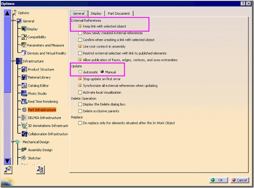
  • Enable external part references and set manual updates for both parts and assemblies. Select Tools | Options.
    Select Infrastructure | Part Infrastructure, activate Keep link with selected object in the External References area and activate Manual in the Update area.

clip_image013
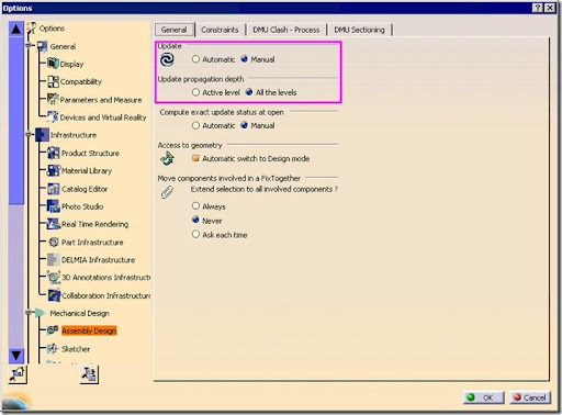
Select Mechanical Design | Assembly Design. Activate Manual in the Update area and All the levels in the Update propagation depth area

clip_image015

Objective: To use top-down assembly methods to create a new associative housing for the gearwheel.

Process: In this project, you will create a new assembly and build a housing for a gearwheel in the context of that assembly.

Instructions

1: Create a new assembly file and change the part number for the assembly to top_down_assemblies_project. Save it as top_down_assemblies_project.CATProduct.

Step 1 - Details

Select File | New and pick Product in the dialog displayed. In the Specification Tree, pick the product. Select Edit | Properties to open the Properties dialog. Edit the part number.

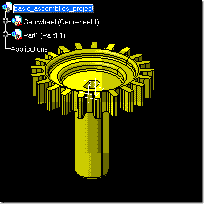
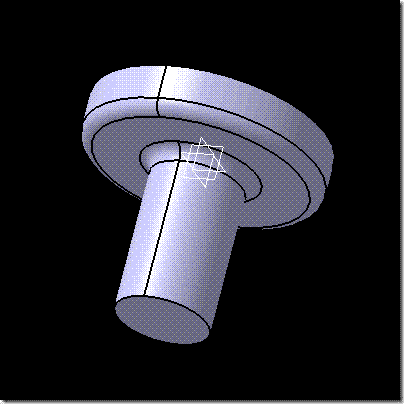
2: Add the existing component ba_gearwheel.CATPart to the assembly.

Step 2 - Details

Select Insert | Existing Component, pick the assembly in the Specification Tree and add the part.

3: Add a new part to the assembly at the assembly origin.

clip_image016

Step 3 - Details

Select Insert | New Part and pick the assembly in the Specification Tree. Click No to locate the new part's origin at the assembly origin.

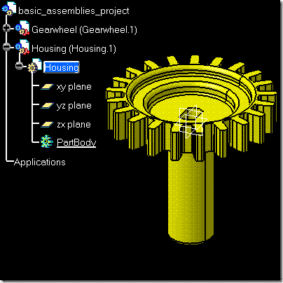
4: Name the part Housing.

Step 4 - Details

Select the new part and select Edit | Properties.

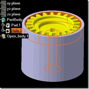
5: Make the new part active in the Part Design workbench.

clip_image017

Step 5 - Details

Expand the tree and double-click Housing to activate it.

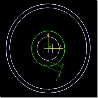
6: Create a sketch on the XY plane consisting of a centered circle whose diameter is offset from the gearwheel by 6mm.
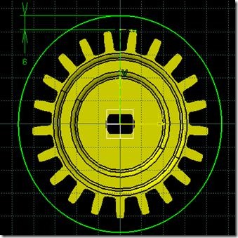
clip_image019

Step 6 - Details

Constrain the sketch center to the gearwheel and create a length constraint between the gear tooth and the circle. If necessary, create construction geometry.

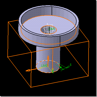
7: Create a pad from the sketch that is as high as the top face of the gearwheel and extends 6mm below the bottom of the gearwheel shaft.
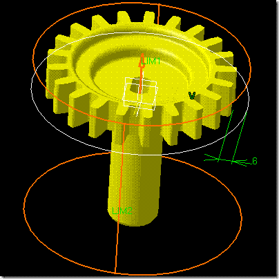
clip_image020clip_image021

clip_image022

Step 7 - Details

Create a pad using the sketch and the Up to plane limits. Pick the top and bottom faces of the gearwheel and set the second limit offset at 6mm.
Or
Create a pad using the sketch and the Up to plane limits. Select Insert | Dress-Up Features | Thickness and pick the bottom face of the pad to thicken.

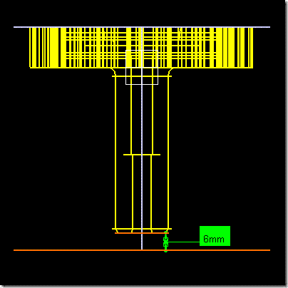
8: Add a counterbore hole to the top face of the pad. Make the counterbore with a diameter of 86mm and a depth of 15mm. Make the hole diameter 25mm and the hole depth 1mm below the bottom of the shaft.

clip_image024 clip_image026

Step 8 - Details

Pick the outside edge of the pad, select Insert | Sketch-Based Features | Hole and then pick the placement face. Picking the edge before activating the command automatically constrains the hole to the center of the pad.
Use Up to Plane for the hole type, pick the bottom face of the shaft for the limit, and 1mm for the offset. The Preselection Navigator can help you pick the bottom of the shaft, or you can try to hide the new part while picking the face.

9: Create a sketch on the bottom face of the pad consisting of a circle offset from the edge of the counterbore hole by 6mm as shown.

clip_image028

Step 9 - Details

Hide the gearwheel from the display.
Change your render style to wireframe by selecting View | Render Style | Customize View and deactivating Shading in the Mesh area.
Use a concentricity constraint between the circle and pad edge, and a length constraint between the hole diameter and the circle.

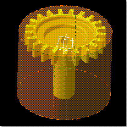
10: Create a pocket that leaves a 3mm thick wall below the counterbore as shown.

clip_image029

Step 10 - Details

Make sure the direction of the pocket points outward. To be sure, preview the feature before creating it. Use Up to Plane for the first limit; pick the bottom face of the counterbore for the limit, and -3mm for the offset.

11: Add 5mm fillets to the edges as shown to finish the simple housing.

clip_image030

Step 11 - Details

Pick the two edges and select Insert | Dress-Up Features | Edge Fillet. The one fillet feature applies to both edges at the same time.

12: Make the gearwheel the active part and change your render style to wireframe.

clip_image031

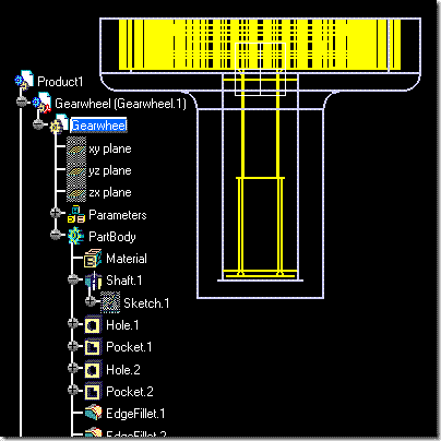
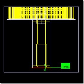
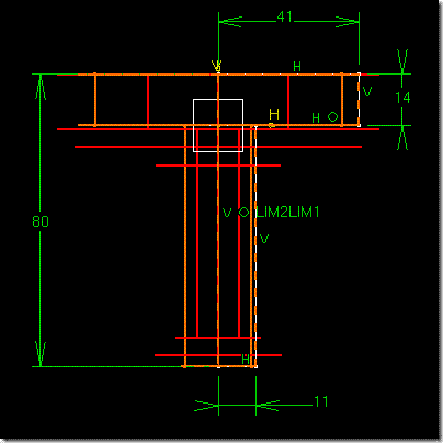
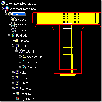
13: Change the height of the shaft feature in the gearwheel from 71 to 80 mm.

clip_image032

Note that the gearwheel part has become red, indicating that it is out-of-date.

clip_image033

If necessary, select Edit | Update. Observe the length of the shaft and the length of the housing.

clip_image034

Note that now the housing part has become red, indicating that it is out-of-date.

Step 13 - Details

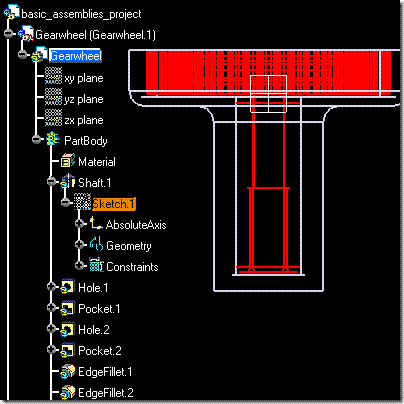
The 71mm dimension is in Sketch.1, which is under Shaft.1 in the Specification Tree.

14: Activate basic_assemblies_project and select Edit | Update. Observe the shaft and housing lengths.

clip_image035

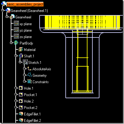
Because of the settings used and the associative construction techniques, the housing will update automatically, keeping the 1mm gap from the bottom of the shaft and the 3mm wall thickness below the counterbore.

Challenge Task: Select File | Save Management to save your work to your working directory.

Review: You can create new parts in the context of the assembly. This is known as a top-down assembly method. Good assembly design uses a combination of this and other methods. Setting CATIA to keep links with to external references allows you to maintain design intent across the assembly.
When designing in context, be aware that when you reference other parts the part definition relies on those links. This practice is typically avoided in most engineering environments because it tends to make manufacturing more difficult and costly. However, you can see that when it is necessary, it is easily accomplished. Generally speaking though, unnecessary links should be avoided as they can create difficulties with PDM systems too.


Creating a Top-Down Assembly

Creating a Top-Down Assembly

Path: Insert | New Part

clip_image002

Use this to ...

  • Create an assembly without all of the components in place. This allows you to start the product design of a component from scratch.
  • Create new components in an existing assembly. This allows you to consider size, space, or interference limitations.

Prerequisites

  • You should be in the Assembly Design workbench.

Process: Creating an Assembly Using Top-Down Techniques

1. Select File | New. The New dialog displays.

clip_image004

2. Select Product from the list and click OK to create the assembly.

3. Edit the properties of the assembly to specify the part number, revision level, and description.

clip_image006

4. Refer to the next process, Creating a New Component Using Top-Down Techniques to create components in this assembly.

Process: Creating a New Component Using Top-Down Techniques

1. Select Insert | New Part. CATIA prompts you to select a component to add the new part to.

clip_image007

2. In the Specification Tree, pick the product. The new part is added to the Specification Tree and displays in the Graphics window. Since this is the first part, the part's origin is automatically positioned at the assembly's origin.

3. Edit the properties of the part to specify the part number, revision level, and description.

4. Add a second part to the assembly. Select Insert | New Part. CATIA prompts you to select a component to add the new part to.

clip_image007[1]

5. Pick the product name in the Specification Tree. Select where to locate the origin of the new part.

clip_image008

6. The new part is added to the Specification Tree and displays in the Graphics window.

7. Edit the properties of the part to specify the part number, revision level, and description.

8. Pick a new part in the Specification Tree, then expand it. Double–click on the Part to begin modeling in context of the assembly. (Make sure you pick the part and not the instance of the part.)

clip_image010

Options

clip_image011

New Part: Origin Point

Allows you to define the position of the new part's local origin.

clip_image008[1]

Yes
Places the new part in the assembly with the new part's local origin at the same position as the origin of an existing part in the assembly.

No
Places the new part in the assembly with the new part's local origin at the assembly's origin.

Tips

  • It's wise to keep track of your parts by renaming them as you add them to the assembly.
  • After creating new components, you can reposition them using constraints.


Design in Context

Design in Context

clip_image001

Overview: There are many advantages to top-down modeling, the greatest being the ability to design or edit in the context of the assembly structure. It is important to understand the following concepts when using design-in-context principles:
- Define the new component before creating any parametric geometry when possible.
- Sketching in the context of an assembly.
- Switching back and forth between top-down and bottom-up methods.
- Creating subassembly files.

Switching Between Top-Down and Bottom-Up

You can use a combination of top-down and bottom-up methods in defining the assembly structure. You can also use a combination of these methods in designing and editing individual component geometry. For example, in an existing assembly, you create a new component and a "black box" shape to define its location and overall size within the assembly structure. You can save this part, close the assembly, and design the detail of the component part using bottom-up methods. The combination of methods provides the best of both worlds: top-down for positioning and evaluating size restrictions and bottom-up for detailing the component without having to work with the entire assembly.

Creating Subassembly Files

Remember, components are the piece parts making-up an assembly. These piece parts can be used in multiple assemblies and multiple subassemblies. Therefore, it is always a good idea for each unique piece part to have its own part file. Even these piece parts can have their own component piece parts. For example, a coupling may be a piece part in a large machine assembly but the coupling also has its own components (plates, shafts, and hardware). The coupling is an assembly itself and a subassembly in a larger assembly. The piece parts in the coupling assembly should not be added directly to the machine assembly as components. Instead, create an empty file to act as the coupling assembly file, such as coupling-assy, and add all of the related coupling components to this file. Now coupling-assy can be added to a larger assembly as a subassembly. When you add a subassembly to an existing assembly, all of the components are added as well. In terms of design-in-context concepts, use the Insert | New Product to create subassembly files before adding or designing new components. Doing it this way creates a subassembly structure that is much easier to manage and manipulate than if you simply add the components to the top level assembly. Be careful of using the Insert | New Component to create a subassembly. If you do this, the subassembly only exists within that individual Product file and cannot be accessed by other CATIA Product files.


Creating a Bottom-Up Assembly

Creating a Bottom-Up Assembly

clip_image002

Path: Insert | Existing Component

clip_image003

Use this to ...

  • Create a bottom-up assembly.

Key Points

  • This technique is similar to building a toy with 'some assembly required.' The necessary components are already available; you just need to put them together.

Prerequisites

  • You should be in the Assembly Design workbench.

Process: Adding a Component to an Assembly Using Bottom-Up Techniques

1. Select Insert | Existing Component. CATIA prompts you to select a product component to add the existing component to.

clip_image004

2. In the Specification Tree, pick a component. The File Selection dialog displays.

clip_image005

3. Navigate to the required part, select it, and click Open. The part is added to the Specification Tree and is displayed in the Graphics window.

4. Position the component with constraints or absolutely.

5. Repeat the process until all assembly components are added.

Sunday, March 9, 2008

Snap and Smart Move

Snap and Smart Move

clip_image002

Path:
Edit | Move | Snap
Edit | Move | Smart Move

clip_image003

Use this to ...

  • Move a component onto another component by snapping similar part geometry together.
  • Move a component onto another component by snapping individual part geometry together and apply constraints.

Prerequisites

  • You should be in the Assembly Design workbench.

Process: Snapping Components Together

1. Select Edit | Move | Snap. CATIA prompts you to select the first geometric element to be used.

2. In the Graphics window, pick the first element on a part. This component moves during the operation.

clip_image005 clip_image007

3. In the Graphics window, pick the second element. This component remains stationary during the operation. CATIA snaps the two components together and displays a green arrow and axis of rotation in the Graphics window.

clip_image008

4. Click the arrow to reverse the component, if necessary.

5. Click in free space to validate the move.

clip_image010

clip_image012

Process: Using Smart Move to Constrain Components

1. Select Edit | Move | Smart Move to display the Smart Move dialog.

clip_image013

2. Click More to expand the dialog.

clip_image014

3. Activate Automatic constraint creation.

4. In the Graphics window, pick an element from the component to move.

5. In the Graphics window, pick an element from the stationary component.
Note that for many element types, CATIA snaps the two components together and displays a green arrow and axis of rotation in the Graphics window.

6. If necessary, click the arrow to reverse the component.

7. Click in the background of Graphics window to add the constraint, and display the message Constraint is created in the dialog.

clip_image015

8. Click OK to close the dialog.

Options

clip_image016

Smart Move Dialog

Allows you to define how a component is moved by snapping and gives you the option of creating constraints.

clip_image016[1]

Automatic Constraint Creation

Activate this option to create a constraint when the component snaps or moves into position.

clip_image016[2]

Quick Constraint

Lets you define the priority with which constraints apply to components. CATIA will apply the first relevant constraint to the type of geometry picked.

clip_image016[3]

Move Constraint Up

clip_image017
Moves a constraint up one level in the Quick Constraint list.

clip_image016[4]

Move Constraint Down

clip_image018
Moves a constraint down one level in the Quick Constraint list.

clip_image016[5]

Create Verified Constraints First

Allows CATIA to create suitable constraints when using the command based on the geometry selected.

Tips

  • You do not have to specify both sets of geometry when using the Smart Move feature. CATIA lets you pick the first geometrical element and drag it onto another similar element before applying a constraint.